Category Archives: Fireworks

Remote Fireworks Launcher

P1010062

The goal of this project was to use a tablet computer to remotely ignite fireworks. The components of the system include:

A bluetooth serial profile is used to wirelessly communicate between the tablet and the control box. For this reason an Android tablet (Motorola XOOM) was used because iOS did not support the serial profile on bluetooth. This provides a range of about 10 yards between the operator with the tablet and the control box. Cabling between the control box and launch box and then launch box to ignites provides an additional 10-20 feet.

Click on the links above for details of each section.

Fireworks Tablet App

Photo Jul 06, 9 46 27 PM

This Android app is the UI for the Fireworks launcher project. Each igniter is represented by a circular button.

UI Description

The row color & outer circle color correspond to the cable bundle & wire color codes respectively. The names of the firework appear in the upper part of the circle and the connection status in the bottom. A green center indicates the igniter status is online, blue have been marked as ignited.

To trigger an ignition, the operator presses the center of a button and drags the finger outward until the outer circle turns red. The further away the finger is dragged the faster a pulsing ring will animate until the distance is sufficient to launch and the outer circle changes to red. Releasing the finger at this point will trigger an ignition sequence. To cancel the touch, the operator can drag the finger closer to the start point until the outer circle turns back to green. Ignite indicatorOnce triggered, the button will flash red/white as long as the igniter is powered (5 seconds by default).

Code Segments

The bluetooth device ID is hard coded in the sources. This was found by browsing for the device with the SENA BTerm app and viewing the properties. When the Connect button is pressed, a connection is made using the bluetooth stack. code segments below.

import android.bluetooth.BluetoothAdapter;
import android.bluetooth.BluetoothDevice;
import android.bluetooth.BluetoothSocket;

    private BluetoothAdapter _bluetooth = BluetoothAdapter.getDefaultAdapter();
    private BluetoothDevice _btdevice;
    private BluetoothSocket _btsock = null;

   OnClickListener mConnectListener = new OnClickListener() {
        public void onClick(View v) {
            _bluetooth.enable();
            _btdevice = _bluetooth.getRemoteDevice("00:12:03:09:70:20");
    		try {
    			ParcelUuid[] uuids = _btdevice.getUuids();
    			_btsock = _btdevice.createInsecureRfcommSocketToServiceRecord (UUID.fromString("00001101-0000-1000-8000-00805F9B34FB"));
    			_btsock.connect();
    		} catch (IOException e) {
    			// TODO Auto-generated catch block
    			e.printStackTrace();
    		}
        }
    };

// when ready to launch
String out = String.format("Launch %d", activeLaunch);
_btsock.getOutputStream().write(out.getBytes());
_btsock.getOutputStream().write(13);

Interpreting the return status stream of data. Each character represents an ignition status that is set into the button state for color coding and animation.

for (int i = 0; i < acount; i++) {
  String arg = args[i];
  if (arg.length() > 0) {
    // first char should be [
    if (arg.charAt(0) != '[') continue;
    int sysstate = arg.charAt(1) - '0';
    FireLaunch.this.controlStatus = sysstate;
    int arglen = arg.length();
    for (int b = 0; b < buttonCount; b++)
    {
      int buttonState = (b < arglen) ? arg.charAt(b + 2) : 2;
      LaunchButton lb = (LaunchButton) MainLayout.findViewWithTag("Button" + Integer.toString(b));
      int displayState = 0;
      switch (buttonState) {
        case '0' : displayState = 3; break; // ready
        case '1' : displayState = 10; break; // launching
        case '2' : displayState = 2; break; // control error/offline
      }
      if (lb != null) lb.setState(displayState);
    }
    lastCloseFrame = SystemClock.elapsedRealtime();
    argIndex++;
  }
}

Fireworks Control Box

Control Box

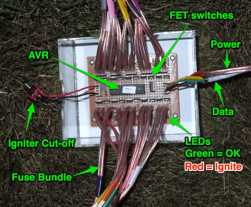
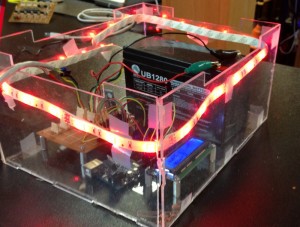
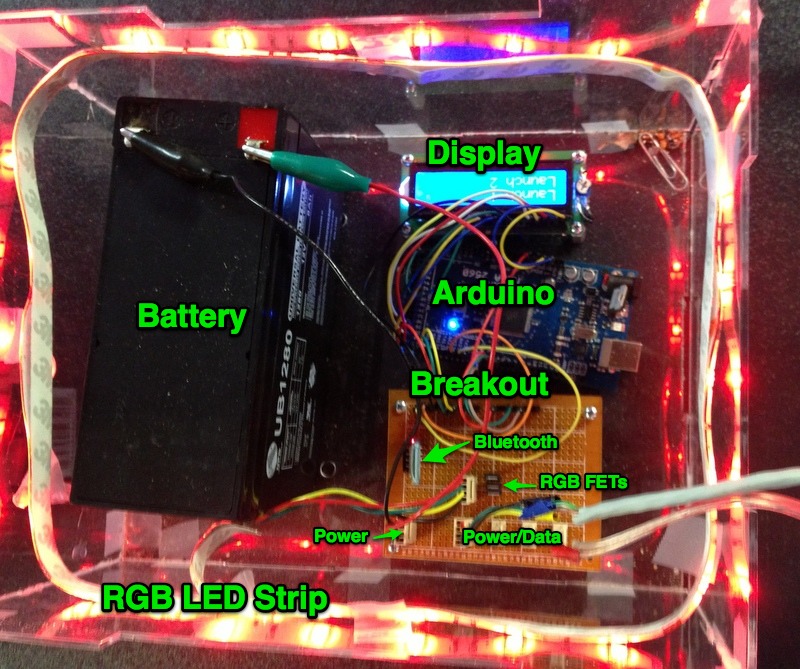
This control box receives commands wirelessly via bluetooth and sends commands to the ignition boxes. It is based on the Arduino Mega. A lesser microcontroller can be used, this was chosen due to availability and multiple UART ports. Having more than one will allow the serial bluetooth to stay connected during reprogramming.

The components of this box are

  • Arduino Mega 2560 
  • 2-line display for debugging, status information
  • Break-out board for connections and bluetooth adapter
  • 12V lead-acid battery to power the controller box as well as all the ignition boxes
  • RGB LED strip for status indication & fun

Controller Annotated

Code Overview

The Arduino Mega is programmed using the standard Arduino IDE with the Wire library to communicate to the ignition boxes and LiquidCrystal library for the display.

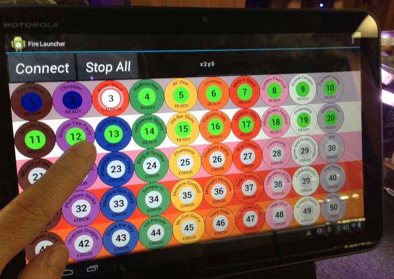
Setup configures the serial ports, LCD pin configurations, Wire configuration as a master device. In the main loop, read a character from the bluetooth serial port and check for a completed command ending in CR or LF characters. If a command is received, display it, scrolling up to display it. If it is a launch command, call the function to trigger the numbered igniter. Also monitor for a heartbeat and go offline if haven’t received a signal from the tablet in 4 seconds.

When a trigger command is received, the TriggerPin method is called. This will use the Wire library to send a command to the corresponding ignition box to activate the pin for 5 seconds.

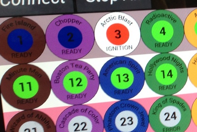
Every second the status of every igniter is sent back to the tablet so it can display which outputs are active. A sequence of 100 characters are sent back with ‘0’ = off, ‘1’ = on or ‘2’ for unknown. The sequence is padded out to 100 if fewer igniter boxes are used. An additional code is sent for the controller status if any, and the whole sequence is enclosed in framing brackets ‘[]’.

The loop also handles color animations for the LED strip. The code currently starts up pulsing green, then flashes blue when a bluetooth connection is made. As long as there is a good connection, it will cycle red/white/blue colors. When any igniter is active, it will rapidly flash red and white.

Code Below

#include
#include

// LCD
LiquidCrystal lcd(22,28,29,27,25,23);
char line1[16];
char line2[16];
char line3[16];
int charpos = 0;
char welcome[] = "Ready";

// Serial Bluetooth
unsigned long timeLastSent = 0;
unsigned long timeLastReceived = 0;
boolean launchSequenceStarted = false;
int launchSequenceIndex = 0;
unsigned long timeLastSequence = 0;

// IC2
byte x[3];
boolean igniterOn[80];

enum cmds {
  CMD_WRITE = 1,
  CMD_WRITE_TIMED,
  CMD_STOP_ALL,
  CMD_READ_PINS
};

struct ic2cmd_write {
  byte addr;
  byte val;
};

struct ic2cmd_write_time {
  byte addr;
  int  time;
};

// PWM LED Strip Vars
int redPin = 4;
int greenPin = 3;
int bluePin = 2;
float stripHue = 0;
float currentRed = 0;
float currentGreen = 0;
float currentBlue = 0;
int colorindex = 0;
unsigned long timeLastColor = 0;
int targetRed = 0;
int targetGreen = 0;
int targetBlue = 0;
float deltaRed = 0;
float deltaGreen = 0;
float deltaBlue = 0;
boolean isFading = false;
unsigned long timeLastFade;
int fadeInterval = 10;
enum LEDmode {
  modeStart = 0,
  modeConnect,
  modeOnline,
  modeLaunch
};
int ledMode = modeStart;

// LCD format for LCD display
String formatn(int val)
{
  String ss = "      ";
  val = val % 100000;
  int negadj = (val < 0) ? 1 : 0;
  String sv = String(val);
  String s = ss.substring(sv.length()) + sv;
  return s;
}

// IC2 Send message to slave to activate igniter
void TriggerPin(int pin)
{
  int slavenum = pin / 20;
  ic2cmd_write_time sc;
  sc.addr = pin % 20;
  sc.time = 5000;

  Wire.beginTransmission(4 + slavenum);
  Wire.write(CMD_WRITE_TIMED);
  Wire.write((byte*)&sc, sizeof(sc));              // sends one byte
  Wire.endTransmission();    // stop transmitting
}

// IC2 send message to stop all igniters
void StopAll()
{
  for (int s=0; s<5; s++)
  {
    Wire.beginTransmission(4 + s);
    Wire.write(CMD_STOP_ALL);
    Wire.endTransmission();
  }
  for (int i=0; i<80; i++) igniterOn[i] = false;
}

// LED Strip Red White Blue pattern
void patternRWB(float shift, float bright)
{
//  shift = 0;
  for (byte i=0; i<16; i++)
  {
    float dist = fmod(fabs(shift + i),16);
    float cdist = dist / 2.0;
    int lcolor = int(cdist);
    int rcolor = (lcolor < 7) ? lcolor + 1 : 0;
    float lweight = 1 - (cdist - lcolor);
    float rweight = cdist - lcolor;
    byte r = byte(min((rwbR[lcolor] * lweight + rwbR[rcolor] * rweight) * bright, 127.0));
    byte g = byte(min((rwbG[lcolor] * lweight + rwbG[rcolor] * rweight) * bright, 127.0));
    byte b = byte(min((rwbB[lcolor] * lweight + rwbB[rcolor] * rweight) * bright, 127.0));
    colors[i * 3 + 1] = 0x80 | r;
    colors[i * 3 + 0] = 0x80 | g;
    colors[i * 3 + 2] = 0x80 | b;
  }
  for (int i = 0; i < 48; i++)
  {
    colors[48 + i] = colors[i];
  }
}

void HSVtoRGB( float *r, float *g, float *b, float h, float s, float v )
{
	int i;
	float f, p, q, t;

	if( s == 0 ) {
		// achromatic (grey)
		*r = *g = *b = v;
		return;
	}

	h /= 60;			// sector 0 to 5
	i = floor( h );
	f = h - i;			// factorial part of h
	p = v * ( 1 - s );
	q = v * ( 1 - s * f );
	t = v * ( 1 - s * ( 1 - f ) );

	switch( i ) {
		case 0:
			*r = v;
			*g = t;
			*b = p;
			break;
		case 1:
			*r = q;
			*g = v;
			*b = p;
			break;
		case 2:
			*r = p;
			*g = v;
			*b = t;
			break;
		case 3:
			*r = p;
			*g = q;
			*b = v;
			break;
		case 4:
			*r = t;
			*g = p;
			*b = v;
			break;
		default:		// case 5:
			*r = v;
			*g = p;
			*b = q;
			break;
	}
}

// PWM LED strip color fade to set value
void fadeTo(int r, int g, int b, int t)
{
  targetRed = r;
  targetGreen = g;
  targetBlue = b;
  float dt = t / fadeInterval;
  if (dt < 0.01) {
    deltaRed = (r - currentRed);
    deltaGreen = (g - currentGreen);
    deltaBlue = (b - currentBlue);
  } else {
    deltaRed = (r - currentRed) / dt;
    deltaGreen = (g - currentGreen) / dt;
    deltaBlue = (b - currentBlue) / dt;
  }
  isFading = true;
}

void DoLEDFade()
{
  if (isFading)
  {
    currentRed += deltaRed;
    currentGreen += deltaGreen;
    currentBlue += deltaBlue;
    int red = currentRed;
    int green = currentGreen;
    int blue = currentBlue;
    analogWrite(redPin, red);
    analogWrite(greenPin, green);
    analogWrite(bluePin, blue);
    if (red == targetRed) deltaRed = 0;
    if (green == targetGreen) deltaGreen = 0;
    if (blue == targetBlue) deltaBlue = 0;
    if ((red == targetRed) && (green == targetGreen) && (blue == targetBlue))
      isFading = false;
  }
}

void setup()
{
  // PC Serial setup
  Serial.begin(9600);

  // bluetooth serial setup
  Serial3.begin(9600);

  // LCD setup
  pinMode(24, OUTPUT);
  digitalWrite(24, 0);
  lcd.begin(16,2);
  // clear buffers
  memcpy(line1, 0, 16);
  memcpy(line2, 0, 16);
  memcpy(line3, 0, 16);
  // print ready message
  lcd.setCursor(0,0);
  lcd.print(welcome);

  // 2-Wire slave communication setup
  Wire.begin(); // join i2c bus (address optional for master)
  memset(x, 0, sizeof(x));
  x[0] = 1;
  x[1] = 1;
  for (int i=0; i<80; i++) igniterOn[i] = false;

  // SPI LED Strip setup
  SPI.begin();
  SPI.setClockDivider(SPI_CLOCK_DIV2);
  SPI.setBitOrder(MSBFIRST);
  rwbR[0] = 30; rwbG[0] = 0;  rwbB[0] = 0;
  rwbR[1] = 30; rwbG[1] = 0;  rwbB[1] = 0;
  rwbR[2] = 10; rwbG[2] = 10; rwbB[2] = 10;
  rwbR[3] = 10; rwbG[3] = 10; rwbB[3] = 10;
  rwbR[4] = 0;  rwbG[4] = 0;  rwbB[4] = 30;
  rwbR[5] = 0;  rwbG[5] = 0;  rwbB[5] = 30;
  rwbR[6] = 00; rwbG[6] = 00; rwbB[6] = 30;
  rwbR[7] = 30; rwbG[7] = 00; rwbB[7] = 00;
  patternRWB(0.0, 1.0);
}

void loop() {
  unsigned long timenow = millis();
  // Read input from bluetooth serial
  if (Serial3.available()) {
    char c = Serial3.read();
    Serial.write(c); // echo to PC
    if ((charpos == 16) || (c == 13)) {
      timeLastReceived = timenow;

      // if this is the 2sec heartbeat, throw away text reset row 3
      if (strncmp(line3, "Online", 6) == 0)
      {
        for (int i = 0; i < 16; i++) {
          line3[i] = 0;
          charpos = 0;
        }
      } else {

        // received end of line, shift line buffers
        for (int i = 0; i < 16; i++) {           line1[i] = line2[i];           line2[i] = line3[i];           line3[i] = 0;         }            // Refresh display         lcd.setCursor(0,0);         lcd.print("                ");         lcd.setCursor(0,0);         lcd.print(line1);         lcd.setCursor(0,1);         lcd.print("                ");         lcd.setCursor(0,1);         lcd.print(line2);         charpos = 0;            // Execute commands         if (strncmp(line2, "Launch ", 7) == 0)         {           int index = atoi(&line2[7]);           TriggerPin(index);           ledMode = modeLaunch;           colorindex = 0;            /* // No launch squencing for 2013           // check for launch sequence start           if (index == 76)           {             launchSequenceStarted = true;             launchSequenceIndex = 76;             timeLastSequence = timenow;           } */   //        Serial.write(line2);         } else if (strncmp(line2, "Stop", 4) == 0)         {   //        Serial.write("Stopping All\n");           StopAll();         }       }     }        // Add received character to buffer     if (c >= ' ' && c <= 'z') {       line3[charpos] = c;       charpos++;     }   }   // check for sequencing   if (launchSequenceStarted && (timenow - timeLastSequence > 20000))
  {
    timeLastSequence = timenow;
    launchSequenceIndex++;
    TriggerPin(launchSequenceIndex);
    ledMode = modeLaunch;
    colorindex = 0;
    if (launchSequenceIndex == 80)
      launchSequenceStarted = false;
  }

  // if we got a signal but in start mode switch to connect mode
  if ((ledMode == modeStart) && (timeLastReceived > 0) && (timenow - timeLastReceived < 500))   {     ledMode = modeConnect;     colorindex = 0;   }      if ((ledMode == modeOnline) && (timenow - timeLastReceived > 4000))
  {
    ledMode = modeStart;
    colorindex = 0;
  }
/*
  if (Serial.available())
    Serial3.write(Serial.read());
*/

//  lcd.setCursor(0,0);
//   lcd.print(formatn(timenow));

  // Once a second, get status from slaves and send over bluetooth
  if ((timenow - timeLastSent) >= 1000)
  {
//    Serial.write("Checking Slaves\n\r");
    // send updates once a second
    timeLastSent = timenow;
    Serial3.write("["); // framing value
    Serial3.write("2"); // System code

    for (int s = 0; s < 4; s++)
    {
      Wire.requestFrom(4 + s, 20);
      byte nread = 0;
      while (Wire.available())
      {
        byte b = Wire.read();
        Serial3.write('0' + b);
        nread++;
      }
      for (int i = nread; i < 20; i++)         Serial3.write('2');           }     Serial3.write("]\r\n"); // framing value   }      // PWM LED strip   if (timenow - timeLastFade > fadeInterval)
  {
    DoLEDFade();
    timeLastFade = timenow;
  }

  switch (ledMode) {

    case modeStart:
    {
      if ((timenow - timeLastColor) > 2000)
      {
         timeLastColor = timenow;
         colorindex++;
        if (colorindex >= 2) colorindex = 0;
        switch (colorindex)
        {
          case 0: fadeTo(0, 0, 0, 1600); break;
          case 1: fadeTo(0, 50, 0, 1600); break;
        }
      }
    } break;

    case modeLaunch:
    {
      if ((timenow - timeLastColor) > 100)
      {
         timeLastColor = timenow;
         switch (colorindex % 2)
         {
            case 0: fadeTo(80, 80, 80, 20); break;
            case 1: fadeTo(120, 0, 0, 20); break;
         }
         colorindex++;
        if (colorindex >= 30)
        {
          colorindex = 0;
          ledMode = modeOnline;
        }
      }
    } break;

    case modeConnect:
    {
      if ((timenow - timeLastColor) > 300)
      {
         timeLastColor = timenow;
         switch (colorindex)
         {
            case 0: fadeTo(0, 0, 100, 200); break;
            case 1: fadeTo(0, 0, 0, 100); break;
            case 2: fadeTo(0, 0, 100, 200); break;
            case 3: fadeTo(0, 0, 0, 100); break;
        }
         colorindex++;
        if (colorindex >= 3)
        {
          colorindex = 0;
          ledMode = modeOnline;
        }
      }
    } break;

    case modeOnline:
    {
      if ((timenow - timeLastColor) > 3000)
      {
        timeLastColor = timenow;
        colorindex++;
        if (colorindex >= 3) colorindex = 0;
        switch (colorindex)
        {
          case 0: fadeTo(100, 0, 0, 1500); break;
          case 1: fadeTo(50, 50, 50, 1500); break;
          case 2: fadeTo(0, 0, 100, 1500); break;
        }
      }
     } break;
  }

}

Fireworks Ignition Box

Ignition Box

Ignition Box

This box receives commands from the control box and powers the nichrome based fuses.

Microcontroller

An Atmel ATMEGA328P was used to for the ignition control. This is the same family of controller as the Arduino, so can reuse libraries from that project. In addition to the price and size savings over an Arduino board, more I/O points are available if the fuses are reprogrammed to remove the use of the RESET pin for I/O instead. All 23 of the available data pins are used, the other 5 pins of the 28 pin package are for voltage. This allows for 20 igniter controls, 2 communication pins (SCL/SDA for clock/data), and one pin for an indicator LED control.

Ignite Box Annotate

Screen Shot 2013-07-06 at 5.16.05 PM

Switch & LED circuit

Each igniter is connected on one side to +12V via the safety cut-off switch. The other side connects to the drain of a low side FET switch. The source of the FET is connected to ground, when the controller activates the gate by going high, a full 12V is placed across the igniter and it heats up.

When there is an igniter connected, a small amount of current will flow from the 12V supply to the 5V supply, lighting the green LED indicating a closed circuit. When the control is activated, the low side of the LEDs in the diagram are brought to ground, causing the red LED to light, indicating the switch is active.

A couple notes about this LED setup: First, there will be a reverse voltage of up to 7V across the LED, make sure the chosen LEDs can support that. Secondly, with all 20 igniters connected, 20 green LEDs will light, causing tens of mA to flow from the 12V to the output side of the 5V regulator which will cause problems for the regulator. To offset that current, additional LEDs are placed between the 5V supply and ground to drain off that current. This also adds some illumination to the box, as seen by the colored lights under each box in the photo below.

Ignition boxes

Ignition boxes

Programming

The program is compiled using AVR studio from Atmel. Instructions on how to program the chips can be found here. This will use the Wire library for serial communications with the controller box, you can copy that library from Arduino.

This is a slave device to the control box, it waits to receive a serial command from the controller. It should get a request every second, if not, it is considered off-line.

Setup configures the pins for output and registers the callbacks for the serial data received event. The controller currently sends two types of commands, either to turn on an output for a specified number of seconds, or to turn off all pins. Each box needs to be programmed with a different serial ID number so they can be addressed separately by the controller, this is done in the Wire.begin(x) call.

The main loop will check if it is time to turn off any pins that have timers set. It will also blink the indicator light depending on the state of the system communications. A serial read request will return the state of all the output pins.

Source code below

#include <avr/io.h>
#include "Arduino.h"
#include <Wire.h>

// pin map so that igniters can be numerically ordered counter clockwise around the chip
byte pinMap[20] = {0, 1, 2, 3, 4, 14, 15, 5, 6, 7, 8, 9, 10, 11, 12, 13, 16, 17, 18, 19};
void receiveEvent(int howMany);
void requestEvent();
unsigned long pinOffTime[20];
unsigned long lastBlinkTime;
unsigned long lastRequestTime;
unsigned int blinkLength = 200;
bool blinkOn;
const byte blinkPin = 22;

bool isIgniting = false;

enum cmds {
CMD_WRITE = 1,
CMD_WRITE_TIMED,
CMD_ALL_OFF,
CMD_READ_PINS
};

struct spicmd_write {
byte addr;
byte val;
};

struct spicmd_write_time {
byte addr;
unsigned int  time;
};

// run once, when the sketch starts
void setup()
{
  pinMode(22, OUTPUT);
  blinkOn = false;
  digitalWrite(22, 0);

  // Set each slave controller to unique address
  Wire.begin(7);                // join i2c bus with address #4 for first slave, 5 for second, etc..
  Wire.onReceive(receiveEvent); // register event
  Wire.onRequest(requestEvent);

// set the digital pin as output
  for (int i = 0; i < 20; i++)
  {
    pinMode(pinMap[i], OUTPUT);
    digitalWrite(pinMap[i], 0);
    pinOffTime[i] = 0;
  }
}

// run over and over again
void loop()
{
  unsigned long now = millis();
  // check if any timed pins should be shut off
  bool anyIgniting = false;
  for (int i = 0; i < 20; i++)
  {
    if (pinOffTime[i] != 0)
    {
      anyIgniting = true;
      if (now > pinOffTime[i])
      {
        pinOffTime[i] = 0;
        digitalWrite(pinMap[i], 0);
      }
    }
  }
  isIgniting = anyIgniting;

  if (now >= lastBlinkTime + blinkLength)
  {
    lastBlinkTime = now;
    blinkOn = !blinkOn;
    digitalWrite(blinkPin, blinkOn ? 0 : 1);
    // if igniting blink fast
    if (isIgniting) {
      blinkLength = 100;
    } else {
      if (now < lastRequestTime + 1500) {
        blinkLength = blinkOn ? 500 : 500; // good connection blink 1 sec
      } else {
        blinkLength = blinkOn ? 100 : 900; // no connection mostly off, blink momentarily
      }
    }
  }
delay(1);
}

// function that executes whenever data is received from master
// this function is registered as an event, see setup()
void receiveEvent(int howMany)
{
  if (Wire.available() == 0) return;

  byte data[8];
  for (int i = 0; i < howMany; i++) {
    data[i] = Wire.read();
  }

  byte command = data[0];

  // command 1 set an output pin
  if (command == CMD_WRITE) {
    // must be 3 bytes: command, pin, on/off
    if (howMany - 1 != sizeof(spicmd_write)) return;
    spicmd_write *cdata = reinterpret_cast<spicmd_write*>(&data[1]);
    digitalWrite(pinMap[cdata->addr], cdata->val != 0);
    isIgniting = true;
  }
  // command 1 set an output pin on, timed shutoff
  else if (command == CMD_WRITE_TIMED)
  {
    // must be 3 bytes: command, pin, on/off
    if (howMany - 1 != sizeof(spicmd_write_time)) return;
    spicmd_write_time *cdata = reinterpret_cast<spicmd_write_time*>(&data[1]);
    digitalWrite(pinMap[cdata->addr], 1);
    pinOffTime[cdata->addr] = millis() + cdata->time;
    isIgniting = true;
  }
  else if (command == CMD_ALL_OFF)
  {
    for (int i=0; i<20; i++)
    {
      digitalWrite(pinMap[i], 0);
      pinOffTime[i] = 0;
    }
  }
}

void requestEvent()
{
  byte state[20];
  for (int i = 0; i < 20; i++) {
    state[i] = digitalRead(pinMap[i]);
  }
  Wire.write(state,20);
  lastRequestTime = millis();
}

// arduino main
int main(void)
{
  init();
  setup();

  for (;;)
    loop();

  return 0;
}

Fireworks Electric Fuses

nichrome wire around a fuse

nichrome wire around a fuse

Electric igniters are made by wrapping a segment of nichrome wire around a standard fuse segment. To make a fuse, you’ll need:

  • a segment of fuse
  • nichrome wire
  • solid core wire
  • hot glue gun
  • electrical tape
  • large gauge wire for cabling

When a current of about an amp is run through small gauge nichrome wire, it will glow orange. This is hot enough to spark ignition in a gun powder filled fuse.

We will be running the entire ignition system off of a 12V sealed lead-acid battery, the type used in UPS backup power supplies. This can provide the high current needed to sustain an amp through the nichrome for several seconds and last for the duration of a fireworks show.

Powered Nichrome

Powered Nichrome

We want approximately an amp through the nichrome, so at 12V we want about 10 ohms of resistance in the of nichrome wire (accounting for a couple ohms of resistance in the 10 feet of connection cables). This equates to about an inch of nichrome wire to wrap around the fuse. Too short and the higher current will cause it to get too hot and break before igniting the fuse. Too long and it wont reach a glowing hot temperature and fail to ignite the fuse. This may take some experimentation to see what length of nichrome will provide a steady glow for your wire gauge (be sure to test with the connection cables as they add some resistance). After wrapping the nichrome, hold it in place with hot glue and tape the ends onto the solid wire.

Fuse cable bundle

Fuse cable bundle

The ends of the nichrome are wrapped around solid core wire that are then connected to a long cable to the ignition box. For this we chose speaker wire, it comes paired and in fairly large gauge (18 AWG) for low resistance when carrying the 1 amp of current to power the nichrome. Each speaker wire is color coded for matching the connector end with the fuse end so you can trace which launch code corresponds to which fuse. 4-pin quick connect housings were used to connect to the ignition board, so two igniter cables per connection. Each half of the ignition box can support 10 igniters, so speaker cables were grouped into bundles of 10 and also color coded.  Then every igniter can be identified by a bundle color & cable color. Eg. the bottom igniter in this photo would be Grey/Black.