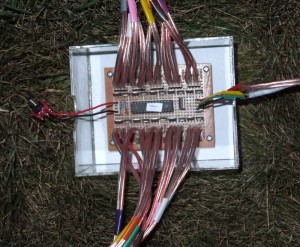
Ignition Box
This box receives commands from the control box and powers the nichrome based fuses.
Microcontroller
An Atmel ATMEGA328P was used to for the ignition control. This is the same family of controller as the Arduino, so can reuse libraries from that project. In addition to the price and size savings over an Arduino board, more I/O points are available if the fuses are reprogrammed to remove the use of the RESET pin for I/O instead. All 23 of the available data pins are used, the other 5 pins of the 28 pin package are for voltage. This allows for 20 igniter controls, 2 communication pins (SCL/SDA for clock/data), and one pin for an indicator LED control.
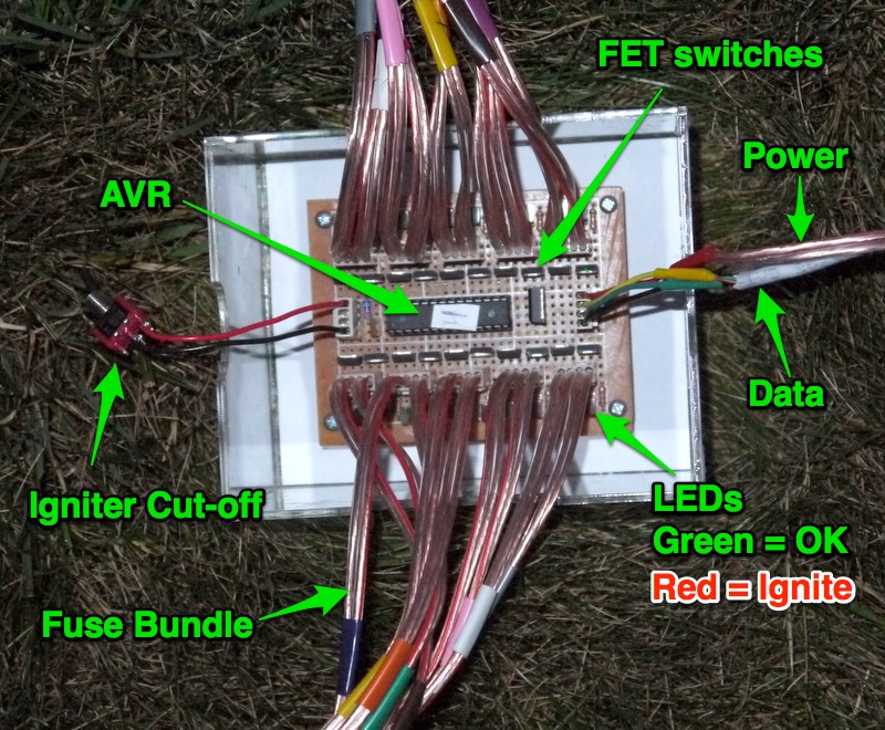
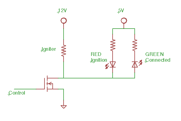
Switch & LED circuit
Each igniter is connected on one side to +12V via the safety cut-off switch. The other side connects to the drain of a low side FET switch. The source of the FET is connected to ground, when the controller activates the gate by going high, a full 12V is placed across the igniter and it heats up.
When there is an igniter connected, a small amount of current will flow from the 12V supply to the 5V supply, lighting the green LED indicating a closed circuit. When the control is activated, the low side of the LEDs in the diagram are brought to ground, causing the red LED to light, indicating the switch is active.
A couple notes about this LED setup: First, there will be a reverse voltage of up to 7V across the LED, make sure the chosen LEDs can support that. Secondly, with all 20 igniters connected, 20 green LEDs will light, causing tens of mA to flow from the 12V to the output side of the 5V regulator which will cause problems for the regulator. To offset that current, additional LEDs are placed between the 5V supply and ground to drain off that current. This also adds some illumination to the box, as seen by the colored lights under each box in the photo below.
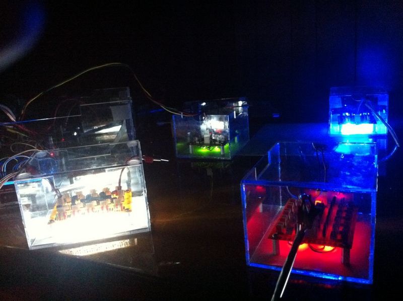
Ignition boxes
Programming
The program is compiled using AVR studio from Atmel. Instructions on how to program the chips can be found here. This will use the Wire library for serial communications with the controller box, you can copy that library from Arduino.
This is a slave device to the control box, it waits to receive a serial command from the controller. It should get a request every second, if not, it is considered off-line.
Setup configures the pins for output and registers the callbacks for the serial data received event. The controller currently sends two types of commands, either to turn on an output for a specified number of seconds, or to turn off all pins. Each box needs to be programmed with a different serial ID number so they can be addressed separately by the controller, this is done in the Wire.begin(x) call.
The main loop will check if it is time to turn off any pins that have timers set. It will also blink the indicator light depending on the state of the system communications. A serial read request will return the state of all the output pins.
Source code below
#include <avr/io.h>
#include "Arduino.h"
#include <Wire.h>

// pin map so that igniters can be numerically ordered counter clockwise around the chip
byte pinMap[20] = {0, 1, 2, 3, 4, 14, 15, 5, 6, 7, 8, 9, 10, 11, 12, 13, 16, 17, 18, 19};
void receiveEvent(int howMany);
void requestEvent();
unsigned long pinOffTime[20];
unsigned long lastBlinkTime;
unsigned long lastRequestTime;
unsigned int blinkLength = 200;
bool blinkOn;
const byte blinkPin = 22;

bool isIgniting = false;

enum cmds {
CMD_WRITE = 1,
CMD_WRITE_TIMED,
CMD_ALL_OFF,
CMD_READ_PINS
};

struct spicmd_write {
byte addr;
byte val;
};

struct spicmd_write_time {
byte addr;
unsigned int  time;
};

// run once, when the sketch starts
void setup()
{
  pinMode(22, OUTPUT);
  blinkOn = false;
  digitalWrite(22, 0);

  // Set each slave controller to unique address
  Wire.begin(7);                // join i2c bus with address #4 for first slave, 5 for second, etc..
  Wire.onReceive(receiveEvent); // register event
  Wire.onRequest(requestEvent);

// set the digital pin as output
  for (int i = 0; i < 20; i++)
  {
    pinMode(pinMap[i], OUTPUT);
    digitalWrite(pinMap[i], 0);
    pinOffTime[i] = 0;
  }
}

// run over and over again
void loop()
{
  unsigned long now = millis();
  // check if any timed pins should be shut off
  bool anyIgniting = false;
  for (int i = 0; i < 20; i++)
  {
    if (pinOffTime[i] != 0)
    {
      anyIgniting = true;
      if (now > pinOffTime[i])
      {
        pinOffTime[i] = 0;
        digitalWrite(pinMap[i], 0);
      }
    }
  }
  isIgniting = anyIgniting;

  if (now >= lastBlinkTime + blinkLength)
  {
    lastBlinkTime = now;
    blinkOn = !blinkOn;
    digitalWrite(blinkPin, blinkOn ? 0 : 1);
    // if igniting blink fast
    if (isIgniting) {
      blinkLength = 100;
    } else {
      if (now < lastRequestTime + 1500) {
        blinkLength = blinkOn ? 500 : 500; // good connection blink 1 sec
      } else {
        blinkLength = blinkOn ? 100 : 900; // no connection mostly off, blink momentarily
      }
    }
  }
delay(1);
}

// function that executes whenever data is received from master
// this function is registered as an event, see setup()
void receiveEvent(int howMany)
{
  if (Wire.available() == 0) return;

  byte data[8];
  for (int i = 0; i < howMany; i++) {
    data[i] = Wire.read();
  }

  byte command = data[0];

  // command 1 set an output pin
  if (command == CMD_WRITE) {
    // must be 3 bytes: command, pin, on/off
    if (howMany - 1 != sizeof(spicmd_write)) return;
    spicmd_write *cdata = reinterpret_cast<spicmd_write*>(&data[1]);
    digitalWrite(pinMap[cdata->addr], cdata->val != 0);
    isIgniting = true;
  }
  // command 1 set an output pin on, timed shutoff
  else if (command == CMD_WRITE_TIMED)
  {
    // must be 3 bytes: command, pin, on/off
    if (howMany - 1 != sizeof(spicmd_write_time)) return;
    spicmd_write_time *cdata = reinterpret_cast<spicmd_write_time*>(&data[1]);
    digitalWrite(pinMap[cdata->addr], 1);
    pinOffTime[cdata->addr] = millis() + cdata->time;
    isIgniting = true;
  }
  else if (command == CMD_ALL_OFF)
  {
    for (int i=0; i<20; i++)
    {
      digitalWrite(pinMap[i], 0);
      pinOffTime[i] = 0;
    }
  }
}

void requestEvent()
{
  byte state[20];
  for (int i = 0; i < 20; i++) {
    state[i] = digitalRead(pinMap[i]);
  }
  Wire.write(state,20);
  lastRequestTime = millis();
}

// arduino main
int main(void)
{
  init();
  setup();

  for (;;)
    loop();

  return 0;
}

