Receiver Hardware
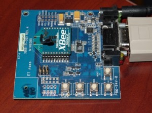
For the receiving module connected to the PC, we will just use the XBIB development board since it already has the serial interface that we need.
Transmitter Hardware
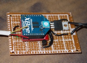
 The end device module only needs a few pins to be wired up for power and the sensor input. For the power provide a 3.3V power supply to pin 1 and GND to pin 10.
Here a LM1117 voltage regulator was used to step down from a 5V A/C adapter. The other component shown is a temperature sensor LM35 attached to ADC1 analog input.
Makeshift Water Sensor
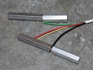
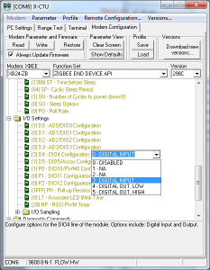
 For the sensor, we will simply use two wires attached to bolts. One wire tied to DIO4 as the sensor input, that has an internal pull-up resistor. The second wire connected to GND. The bolts are placed on the floor near each other, but not touching. When water touches them both, it will make a circuit connection pulling the input low.

